Glad you asked.
Like many answers to many questions, the answer here is “sometimes yes, sometimes no.”
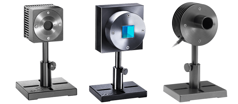
To explain this, we must look at each of the three main types of laser power/energy sensors:
- Photodiodes
- Thermal-based, or thermopiles
- Pyroelectric (energy sensors)
Within each category, we also need to consider any optical coatings and/or accessories (e.g., filters, diffusers, etc.).
Here’s a graph of Ophir’s main power and energy sensor types, showing their relative angular dependencies:

Let’s say 98% is an “excellent” response, and 90% is “okay.” If one wants an “excellent response,” he could use the BF/PF sensors practically at any angle, the Pyro (BB) sensors up to 40°, Thermal (BB) up to 30°, and Photodiode (BB) up to about 15°. Most other photodiode sensors as well as diffuser-based pyros cannot be used past 10°.
If, however, one only needs an “okay” response of 90%, things are even easier. Almost all thermal and pyro sensors (except diffuser-based) can be used past 50°, and the Photodiode (BB) can be used up to 40°. Note that even in this case, most photodiodes and PExx-DIF (diffuser-based pyro) sensors cannot be used at a very steep angle.
So that’s the what.
Now here’s the why…
Photodiodes
Let’s start with photodiodes, used for measuring low power lasers.
The main factor that affects angular dependence in PD sensors is the filter, or multiple filters used to lower the incoming laser power.
The bare photodiode is extremely sensitive so filters are usually a must.
Ophir sensors come with one filter built-in and another detachable filter to widen its dynamic range:

To understand why filters must be used head on, we must think about how a filter works. Namely, it absorbs a portion of the incident laser power. The thicker the filter, the more it can absorb, as the laser must cross a larger distance. If a laser hits the filter on an angle, this will increase the optical path, as shown below:
")
This explains why angular incidence has such a strong effect on photodiodes (other than the BB, which uses a special coating rather than a filter). Note also that photodiodes with filter “in” (i.e., double filtering) experience a rather severe angle dependency.
Finally, examine the curve for Photodiode (BB). Note that it, too, is slightly angle-dependent. The reason for this minor effect is that the higher the angle (the more it approaches a glancing angle), the more the surface of the photodiode reflects the laser beam. So in this case, the lower absorption in the sensor isn’t due to a higher absorption in the filter (since there is no filter), but rather it reflects a lower absorption overall.
Thermal Sensors
Thermal sensors are not subject to the issue of optical paths in filters.
First, most thermal sensors don’t use filters, being able to withstand much higher powers.
More importantly, though, is the fundamental difference between thermopiles and photodiodes: Photodiodes use semiconductors to convert light into an electric signal, while thermopiles convert heat into the signal.
Therefore, even in the case of thermal sensors with volume absorbers (whose thickness does affect optical path as in the case of the PD filters), angle doesn’t plays much of a role in the measurement. The light absorbed in the PD filter is not being measured, so it certainly is important to know how much of it passes through. However the heat generated in a thermopiles coating continues onwards to the sensor and is measured.
That’s why in the graph above, both thermal sensor coatings (BB – surface, and PF – volume) stay almost the same regardless of angle.
At steep angles, however, the issue of high reflection at glancing angles becomes a factor, which is why even thermal sensors aren’t completely independent of angle.
Pyroelectric Sensors
This brings us to the final group of sensors – pyroelectric-based sensors, used for measuring pulsed laser energy.
Pyro sensors work on a completely different, third principle.
Here’s how Ophir Product Manager Mark Slutzki explains it (link at the end of the post for his full white paper on incidence angles):
“The laser pulse is absorbed by an absorptive material and becomes a heat pulse; the resulting acoustic pulse in a pyroelectric crystal (skipping over many details) finally becomes a measurable voltage signal proportional to the laser pulse energy.”
So, like in the case of thermal sensors, optical path is not an issue here. So that explains why the pyroelectric graphs are almost completely impervious to incidence angle.
Except one.
Note that “Pyro (DIF)” is highly subject to changes in angle.
The reason for this is pyro-dif sensors (usually seen as PExxxx-DIF-C, such as PE50BF-DIF-C) have a diffuser attached to the front.
Unlike a simple attenuating filter or volume absorber, a diffuser acts differently for different angles, even with thermal or pyroelectric sensors.
Why?
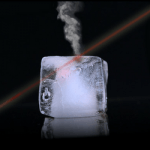
A diffuser is used to make the laser beam larger. When the power density is too high, an expanded beam goes great lengths to make this much lower.

But what happens if the beam isn’t coming head-on?
It will look like this:

Part of the laser completely misses the sensor (indicated by a circle).
That is why “Pyro (DIF)” shows much lower absorption past 10 or 20°.
Summary
I like the graph above, but maybe another way we can view this data is with a chart. Let’s see the maximum angle for each sensor, both at 98% absorption (“excellent”) and 90% (“okay”):

Here’s the original white paper from Mark: How is laser Power/Energy measurement affected by incidence angle?

Leave a Reply
Your email address will not be published. Required fields are marked *