Laser power sensors are the key to efficient and effective use of your laser system, whether you use it in a factory, medical facility, or research institution. To ensure the laser power sensors themselves remain accurate, they must be calibrated regularly. When you receive the sensor back from calibration, you will see a certificate of calibration (CoC) like this:
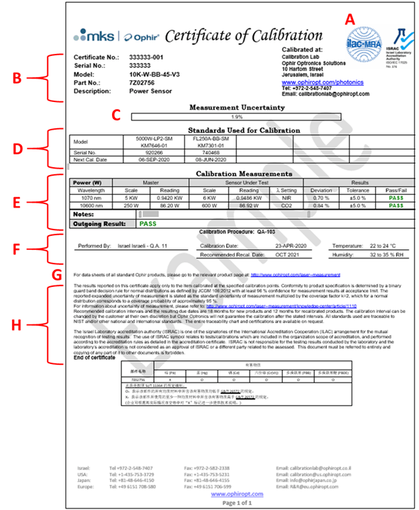
This looks like a typical official document, but it may be difficult to understand the significance of each section. Let us examine this document one piece at a time:
A. ISO17025 Accreditation Logo:
This logo is standard for most Ophir catalog sensors. It means that the calibration process used for the device is in compliance with ISO17025 standard as certified by our ISO17025 accreditation. For more information about ISO17025 visit our website: https://www.ophiropt.com/laser–measurement/ISO-IEC-17025.
B. Sensor Parameters:
All parameters needed to identify the device being calibrated and the particular certificate in question. This section will always include the serial number of the device, along with the “certificate number,” which is the device serial number with an identifier that indicates what number certificate it is for the particular device. In addition, there is a model number and sensor description.
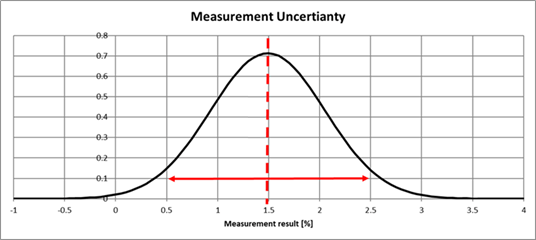
C. Measurement Uncertainty:
In this case, “measurement” refers to the calibration, i.e., the process of comparing the reading of the device under test (DUT) with the reading of an accurate calibration master. In an ideal world, the calibration master would be errorless, noiseless, and absolutely correct, in which case the measurement uncertainty would be zero. If the measurement uncertainty is zero and the calibration result is 1.5%, we know with 100% certainty that the DUT was off by 1.5% from the absolute true value in that particular measurement.
However, due to uncertainties in the NIST calibration, calibration transfer error from the NIST reference to our working reference, as well as setup instabilities, the calibration uncertainty is not zero and the DUT may be off from the real value by more or less than what was measured. For illustration, see the graph below, which shows a range of possible results which could hold the real deviation of the DUT. In this case, the probability of the results follow a normal distribution.
The calibration uncertainty is important for deriving pass/fail criteria used to determine whether a device is meeting its accuracy specifications.
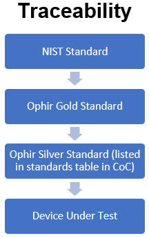
D. Standards
The standards table lists the reference standards used for the calibration measurements. Part of having ISO17025 accreditation means that every measurement instrument used in the calibration, such as calibration masters and multi-meters, must also be calibrated by an ISO17025 accredited laboratory with traceability to NIST (or a different national standards laboratory). Here is an example of a traceability chart:
E. Calibration Measurements:
This table contains all the relevant measurement parameters and results. All Ophir CoCs will include the following columns in the calibration results table:
- Results: the raw data reading of the reference sensor and device being calibrated
- Deviation in [%]: amount that the device deviates from the reference
- Tolerance of the measurement in [%]
- PASS/FAIL statement
For further explanations on the meaning of these terms see our blog post on PASS/FAIL statements.
- Information about the specific calibration, with a reference to the procedure number, who performed it, the date, and environmental conditions.
- A reference to the Ophir website where sensor datasheets can be found.
- Information relating to the calibration and accreditation. Particularly, the decision rule used to determine if a sensor passes or fails calibration and the resulting confidence level. In the example CoC here, the confidence level is 96% at the acceptance limit. This means that there is a worst case 4% risk that the sensor slightly deviates from the specification.
For more information about calibrating your laser power sensor, feel free to reach out to your local representative.


Leave a Reply
Your email address will not be published. Required fields are marked *