Over 55 years ago, optical fiber was already contemplated as a more reliable alternative to copper wire in telecommunications. Optical cable can carry much more data than copper wire, is free of electromagnetic interference, and ensures less loss of a signal due to attenuation or noise.
Just to get an idea of the difference, research has shown that copper cable can lose 94% of the signal over a distance of only 100 meters, while optical cable loses only 3% over the same distance!
Lasers and LEDs for optical telecom will usually be in the near-infrared (=NIR) range of 1260 to 1625 nm, instead of visible light. This is because there are fewer losses due to attenuation and dispersion of a signal as the wavelength increases–so it’s preferable to use NIR wavelengths. However, using optical signals for telecom has its own unique problems:
- For testing the equipment, you need specialized sensors for the spectral range and power range used in telecommunications.
- There are losses as a beam exits a fiber, going either into another fiber, or into free space. For this, we may require a fiber optic adapter and connectors.
- Since the beam diverges upon exiting a fiber, we may require an integrating sphere to capture the entire beam.
Sensors for Telecom Lasers
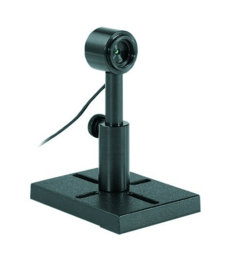
Telecom applications can employ lasers over a very wide range of powers–which requires sensors suitable for anywhere from 10 picowatts to 300 milliwatts. Photodiode detectors, such as Ophir’s PD300-IRG (Fig. 1), are specially designed for monitoring Telecom wavelength signals, both from an optical fiber or through free space. The PD300-IRG has a spectral range of 800 nm to 1700 nm, and a power range of 10 picowatts to 200 milliwatts.
Analyzing the sensor output
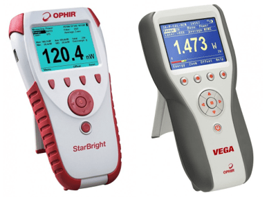
There are a number of options for analyzing the sensor output. The output can be read out by a suitable stand-alone meter, such as the StarBright or Vega meter (Fig. 2). Ophir’s meters are “plug-and-play”, so the sensors and meters can be interchanged and each sensor’s calibration and related data moves with the sensor. Also, Ophir meters can be hooked up to a PC by means of an RS232 cable, a USB cable, or an Ethernet cable, depending on the model of the meter.
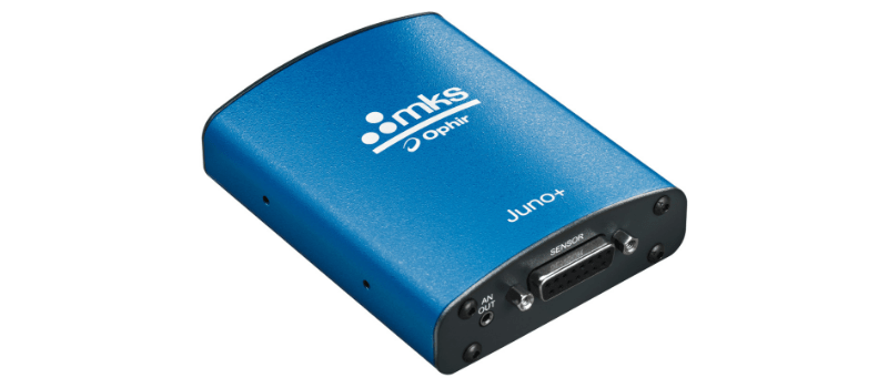
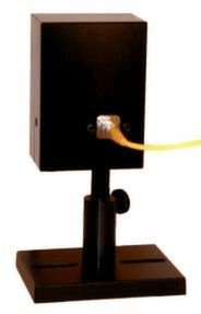
There are also PC interfaces, such as the Juno+ (Fig. 3), which allows data to be read out directly from the sensor to a PC. Also, you have the option of using Ophir’s LabVIEW software, in order to analyze the data, or using any other data analysis tool on your PC.
Fiber Optic Adapters and Connectors
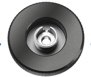
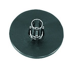
When connecting a fiber to a detector, there are special connectors and adapters for different fiber types. Different fiber types you may encounter are an FC (Ferrule Connector—Fig. 4), or an ST (Straight-Tip—Fig. 5), and the like. These may require a bracket to hold the fiber in place on the sensor.
Integrating Sphere Sensors
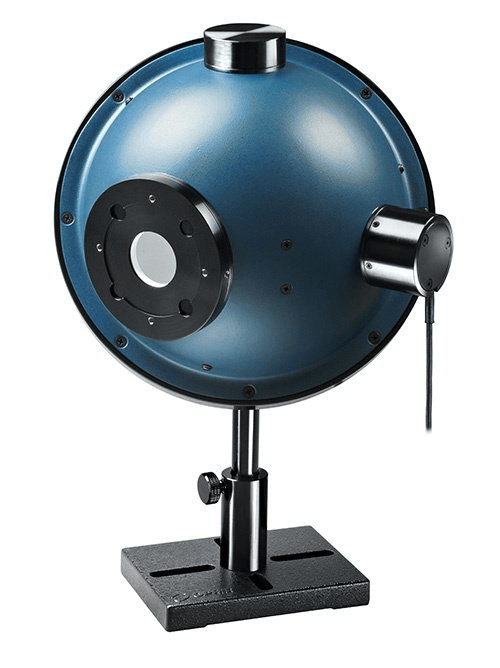
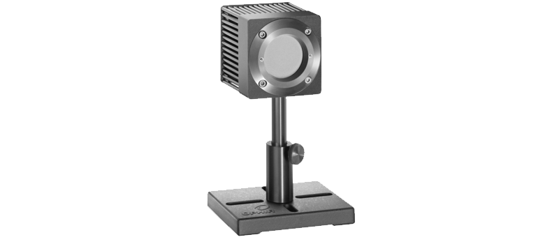
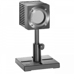
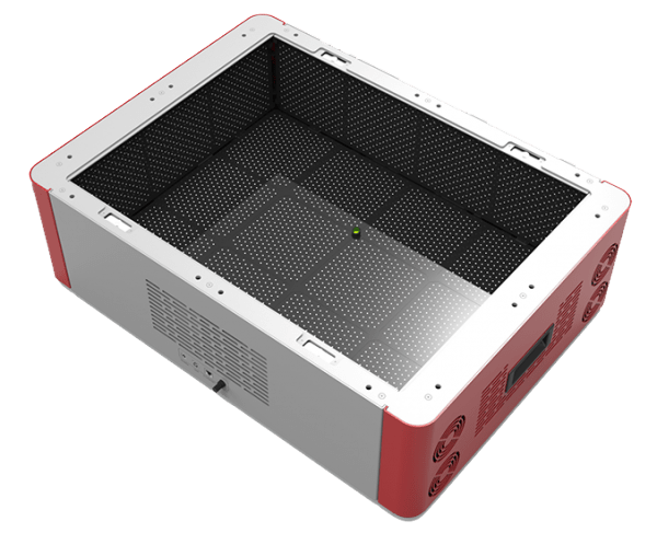
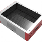
If a beam diverges significantly upon leaving an optical fiber, an integrating sphere should be added to the sensor to capture the beam. (If we’re dealing with an optical fiber with a low numerical aperture, we can use a photodiode sensor without an integrating sphere). For example, the 3A-IS-IRG (Fig. 6) is a photodiode sensor with an integrating sphere that can capture beams with divergence angles up to ±40 degrees. There are also larger integrating spheres that can be fitted and calibrated with a variety of detectors, such as the IS6-D-VIS (Integrating Sphere 6”-Divergent-for visible-light detectors–Fig. 7).


Leave a Reply
Your email address will not be published. Required fields are marked *