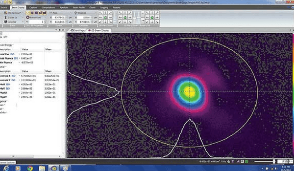
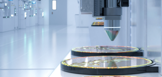
In certain cases where a beam or focused spot diameter is in the order of tens of microns in diameter special attention is required when it comes to beam profiling. One example is stent cutting where a high power laser is focused down to a small spot which can be smaller than 10 micrometer. Ophir photonics offers two types of beam profilers that can be used: CCD cameras and scanning slit profilers, and each type has advantages and disadvantages.
CCD cameras
CCD cameras are commonly used for many beam profiling applications as they provide a complete ‘real time’ high quality measurement of a laser beam. However, using a CCD camera for profiling such a small beam presents several challenges:
- Resolution: a CCD beam profiler measures the spatial intensity distribution of a light beam using a 2D array of thousands or millions of CCD pixels. In order for a camera beam profiler to display spatial changes of intensity in high resolution the beam diameter has to be significantly larger than the spacing between pixels in the array. The rule of thumb is that a beam has to be at least 10 times larger than the pixel spacing and preferably 100 times larger or more. For example, Ophir-Spiricons SP620U camera has a pixel spacing of 4.4 micrometer therefore beams of ~40 micrometer diameter or less cannot be profiled directly using this camera.
By appropriately magnifying a small spot beam before profiling it, one can easily overcome this problem. Ophir-Spiricon offer two types of magnifying accessories, re-imaging beam expanders and microscope objective lenses, both of which can easily mount on to the camera. The Beam expander enlarges a beam by about four times a collimated or nearly collimated beam. To profile a focused beam, microscope objectives may be used to magnify up to ×22.
- Damage threshold: in stent cutting for example as well as in many other material processing laser applications the laser beam is not only very small but has very high power as well. Focusing the beam down to small spots results in extremely high power density which can easily be in the order Mega watts per cm squared. Such high power density levels are sufficient for cutting steel or even diamond but can easily damage a camera system. The direct power density that a CCD can handle without damage/saturation is in the order of micro watts per square cm.
Although expanding a beam reduces the power density it typically doesn’t reduce it below a CCD cameras damage threshold. Proper attenuation is needed for profiling the beam. Ophir-Spiricon offers various beam splitters and ND glass filters that can easily be mounted on to a camera to properly attenuate a beam for profiling.
Combining these components to attenuate a beam can require special attention. A single beam splitter in a beams path reflects the vertical S polarization component at a higher intensity than the plane P polarization component. The disparity in polarization could lead to unreliable measurements. A user may be interested in using two beam splitters in order to equalize S and P reflected polarization. Ophir-Spiricon offers camera accessories that combine two beam splitters with filters for this purpose.
Scanning slits
Scanning slit beam profilers can be used for very small beam spots, depending on the scanning slit size. Ophir-Photon offers scanning slits that can profile beams as small as 4 micrometer.
Using a scanning slit, there is usually no need or very little need for attenuation as the slit performs as a physical attenuator; only a very small fraction of the beam hits the sensor at a time. However, there are two disadvantages with a scanning slit:
- Lack of detail: One can not see full details of a beams two dimensional intensity distribution using a scanning slit. As opposed to as camera a scanning slit does not provide a complete ‘real time’ image of the beam. The software of a scanning slit uses an algorithm to create an accurate approximation of a beam’s intensity distribution. The approximation is good to visualize the general size and shape of the beam but it could lack in detail. Therefore its main applications are laser beam diameter measurements for Gaussian types.
- Slow pulsed lasers: a scanning slit beam profiler is a mechanical system that samples the intensity across a beam and uses the samples to construct a piecewise picture of the beam profile intensity. In order to obtain accurate measurements using a scanning slit profiler there must be a sufficient number of pulses during the time the slit sweeps through the beam to generate a meaningful profile. The minimum laser pulsing rate a scanning slit can measure depends on the beam size and the scanning speed. Typically, a pulsing rate has to be at least 1 KHz, and preferably much more.

You might also like to read: A Shopping List for Your Beam Profiler
Share this:


Hello,
First of all thank you for this very useful blog.
At our company we use BeamStar FX 33, and I want you to clarify something for me please.
when ,in the datasheet, you say that “with the filters installed, the value will increase by a factor of 2*10^4 to 10^6 depending on wavelength”
Can you please tell me which wavelength is related to which factor?
Thank you in advance for your answer.
Here’s a graph of our ND filter transmission for wavelengths from 400 nm to 2200 nm:
The red line is ND1 and the black is ND2. A camera generally comes with 1 ND1 filter and 2 ND2 filters. Additional filters can be purchased as needed. So, depending on the filters you’re using, you can check the above chart to see the actual transmission for your laser’s wavelength. Just multiply all the filter transmission values to get the total transmission (through all the filters), and the inverse of that number is your factor.
(Note if you do the calculations based on this chart, assuming one is using all three filters included with the camera, you’ll notice that the factor can be far higher and lower than the range you mention. I suspect that the range of 2×10⁴ to 106 is for a small section of the chart, seemingly the visible range. At infrared wavelengths, the filters are less effective and the factor will be lower. And in the UV range, the factor can be much higher.)
Effy