Sensors used for measuring laser power or energy should be calibrated regularly. Frequently, customers sending a sensor to our calibration laboratory for the first time will neglect to include the accessories that go with it. The consequence is that the calibration cannot be carried out, causing delays.
But which sensors have specific accessories – and what does that mean, exactly?
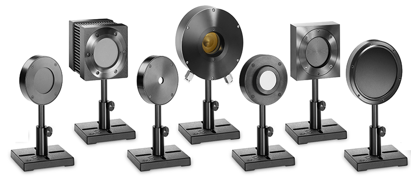
Sensor accessories
In fact, many sensors across the different product groups have specific accessories. As a rule, these are removable filters, diffusers or protective windows that were calibrated together with the sensor as a unit. The calibration data — of the sensor plus its accessories — are stored in the sensor itself, and the display device (e.g. power meter) reads out the corresponding data records. Sensor-specific accessories cannot be used with any other sensor, even an identical model. If sensor-specific accessories are swapped, it can lead to considerable deviations in the measurement.
Especially with our long-lasting sensors, it’s easy to forget where the sensor’s accessories are activated or where their use is displayed. Nevertheless, with a few exceptions for OEM sensors, the relevant parameters (e.g. wavelength, measuring range, power/energy and potentially pulse length) must be entered by the user via the device’s display or its software (StarLab). Our TechTips for each sensor group contain useful information on this.
Let’s consider some examples by sensor type.
Thermal sensors
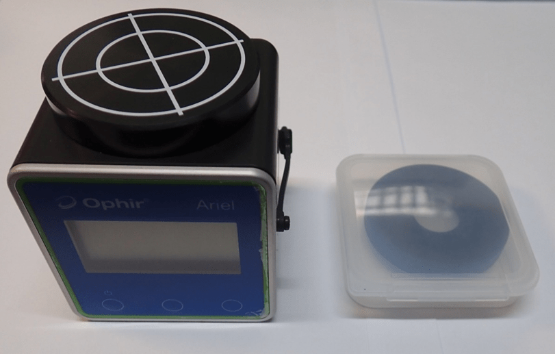
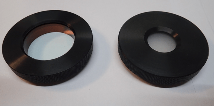
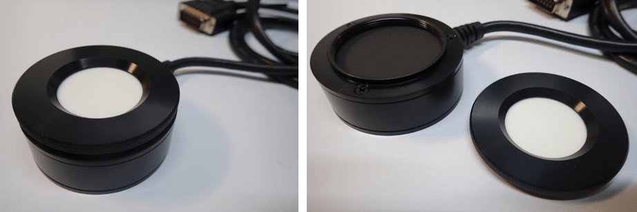
Let’s start with the Ophir Ariel all-in-one sensor (PN: 7Z02798). This compact power meter with integrated display function has a special feature: The scope of delivery includes both a removable diffuser and a protective window, all of which must be sent in for calibration.
The Ophir Ariel instrument must always be calibrated together with its sensor-specific diffuser and protective window.
Our TechTip:
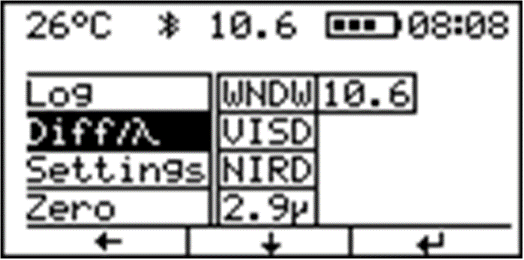
The settings (Diff) of the Ophir Ariel gage show which setup is currently configured. Here, you can set which measurements the device is to be used for, depending on which accessories are attached.
‘WNDW’ is selected when the protective window must be used, or ‘VISD’ and ‘NIRD’ when the diffuser must be used. Measurements at 2.9 µm or 10.6 µm require neither protective window nor diffuser.
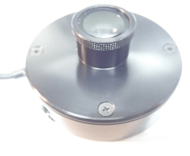
Another example of a thermal sensor with specific accessories is the Ophir 3A-FS measuring head (PN:7Z02628)
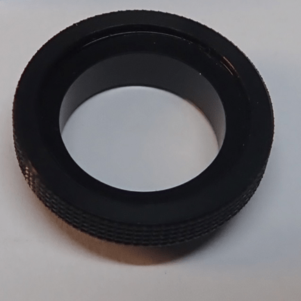
Our TechTip:
For all wavelengths above 2200nm that are measurable by the sensor, the protective window must be dismounted and ‘OUT’ must be selected as the setting on the display unit. If the window is not removed, it can be damaged or even pierced.
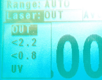
For all wavelengths between 190 nm and 2199 nm, the appropriate range ‘<2.2 / <0.8 / UV’ must be selected and the protective window must be mounted. If, for example, a laser with 1064nm wavelength is to be measured, the protective window must be mounted onto the sensor and the setting ‘<2.2’ must be selected.
Pyroelectric sensors
Our TechTip:
With this pyroelectric sensor, you must manually set whether the diffuser is screwed onto the sensor or not. The selection can be viewed on the respective display device, in this case an Ophir NOVA 2:
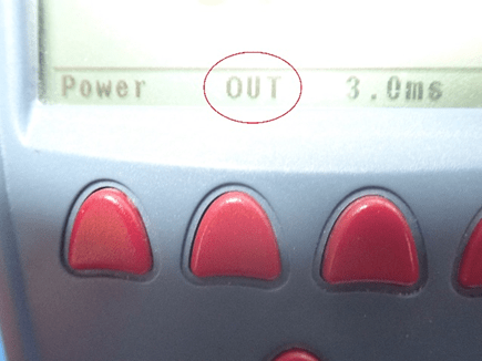
To change the settings to ‘IN’ for the diffuser, just press the red button under ‘OUT’. The following window will then appear in the display:
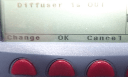
Upon pressing the red button under ‘Change’, the following info appears in the display of the NOVA 2:
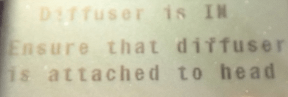
Confirm with the red button under ‘OK’.
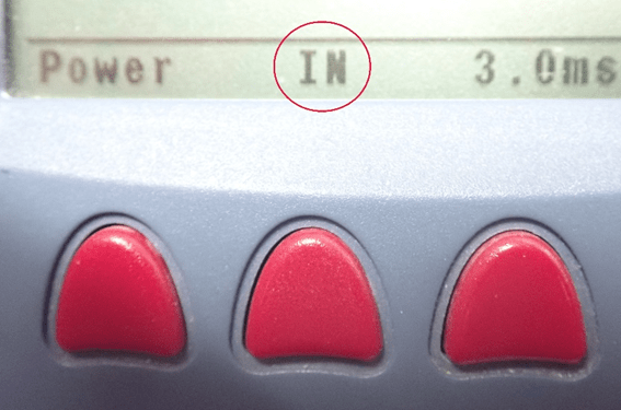
- The setting ‘OUT’ changes to ‘IN’, and the diffuser must be mounted.
Photodiode sensors
With standard photodiode sensors, the filter has a sticker on its side that clearly indicates which sensor it belongs to. The sticker design has changed over time, but two examples follow. The photodiode sensor itself also has a sticker with identifying details, so the two components can be easily associated.
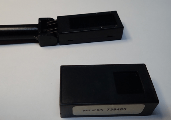
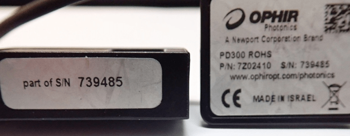
Figure 14 shows that this specific filter (left) is associated with this specific sensor (right), as they share a common serial number: ‘S/N 739485’. Serial numbers are unique to any given device, as they are only ever assigned once.
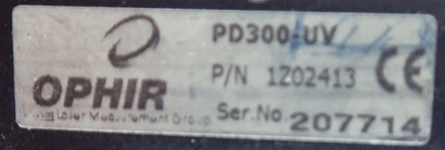
In contrast, the stickers on older filters show additional information – but this is about the sensor. The filter shown in Figure 15 belongs to the sensor PD300-UV PN:1Z02413 SN:207714. In this case, the shared serial number (207714) is proof of assignment to that sensor.
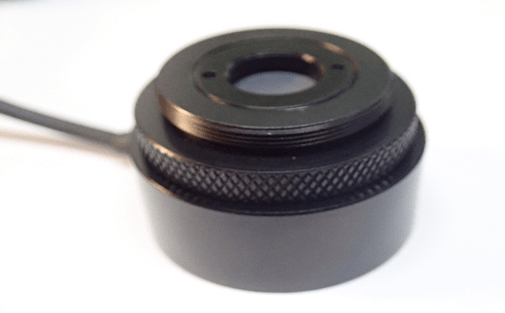
Also for this Ophir photodiode sensor PD300R-3W (PN:7Z02437), the filter is absolutely considered a part of the sensor.
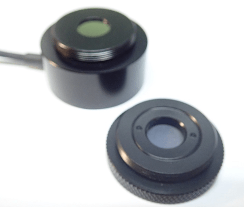
Our TechTip:
Here, too, it must be manually set on the respective display device whether the sensor is used ‘with’ or ‘without’ filter. The images below show the display of an Ophir NOVA 2 device. At the bottom left of the display, you can see whether the filter is ‘OUT’ or ‘IN’.
In Figure 18, circled in red you can see that the word ‘Filter’ is displayed in negative text (white font on a black background). This indicates that the filter is switched to ‘active’ and must be used.
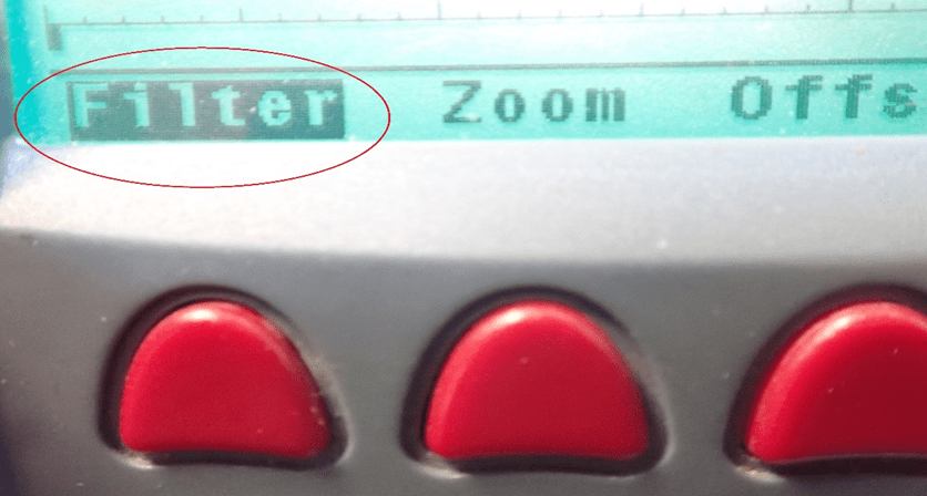
To change the sensor setting to ‘without filter’, the red button under ‘Filter’ must be pressed once. A new window then opens in the display (Figure 19).
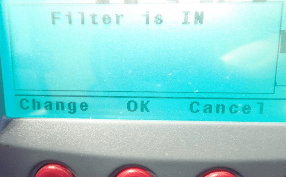
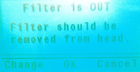
Then press the red button under ‘Change’ and confirm with the red button under ‘OK’. The following image shows what is displayed once ‘Change’ has been pressed:


Leave a Reply
Your email address will not be published. Required fields are marked *