A few months ago we posted a blog with several examples of cases where beam profilers helped manufactures and companies. Here are a few examples where a beam profiler was used to indicate and repair lasers that malfunctioned in the medical industry.
CO2 Laser Waveguide Medical Delivery System
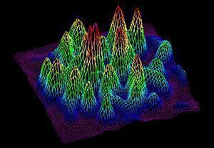
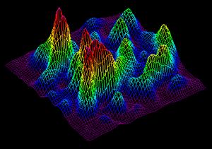
Figure 1 shows the output of a flexible waveguide delivery system for CO2 lasers in a medical application. When the waveguide is held straight or only bent slightly, the beam is quite uniform. Figure 1 shows the beam pattern with slight bending of the waveguide. Notice that the beam is broken into many lobes and hot spots. However, these hot spots move around very rapidly with only slight bending of the waveguide delivery system, and thus a fairly uniform average energy is applied to the patient. Figure 2, however, shows the same waveguide with heavy waveguide bending. Now the beam has become much less uniformly disbursed, and the hot spots are coming together and leaving cold spots with large areas of low energy. In this case the motion did not make up for the poor distribution of energy, and uneven processing was performed with the laser. The hot spots became too concentrated to obtain uniform delivery to the patient.
Tissue welding- medical research
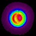
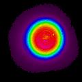
A CW Erbium YAG laser in the 1.5mm range was used in a medical experiment for tissue welding. It was found that with exactly the right energy density at this wavelength, animal tissue could be welded together. Figure 5 shows the output of this beam with poor alignment of the delivery system. Using this beam the tissue welds were very poor, and failed under a very small amount of stress. Figure 6 shows the same laser with the delivery system properly aligned. In this case the beam is a nice uniform flat top, and it gave excellent performance.
In laboratory experiments this laser was used to weld together a severed vein in a mouse’s leg. It was determined that using a well aligned beam, the vein could be welded such that the weld area was as strong as the rest of the vein. With poor alignment of the laser, the veins ruptured very quickly undervery low pressure.
You might also like to read: Laser Measurement in the Medical Industry
Share this:


Me parece muy interesante la prueba, podrian decirme el diámetro de la vena soldada
I find it very interesting test, could you tell me the vein diameter welded
Dear Jorge, thank you for your comment, though we are sorry but we cannot answer your question. We suggest you ask an expert in the medical field for an answer.
If you have a question in the photonics measurement field, we will be happy to reply
I have been thinking about going into the medical field lately but not as a doctor or a nurse. I was thinking more like medical device development. I would love to test medical software and electronics. I just don’t know what kind of schooling I would need for that. Great post, very interesting.